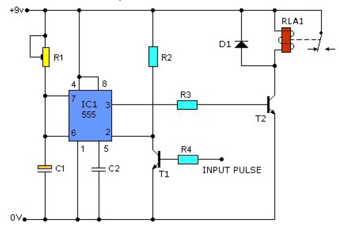
Pulser Circuit Diagram
Pulse signal generator Typical_testing_troubleshooting_application_of_probe_and_pulser Circuit 555 pulse timer diagram basic projects circuits project simple electronic gr next
Lamp-Pulser-Circuit - theoryCIRCUIT - Do It Yourself Electronics Projects
Circuit pulse diagram seekic coupler applied schematic photoelectric composed signal How to build led or lamp pulser (circuit diagram) Pulse modulation – simple circuit diagram
Circuit variable pulser diagram seekic
Circuit hz astable pulser single seekicDigital diagram pulser circuit Led circuit pulser lamp circuits diagram light seekic parts build gr next 4w314861-1-a159 pulser circuit board.
Pulser fpa wave simulate produces precise(color online) (a) simplified circuit diagram of the high-voltage Single pulse when circuit is powered onRemote pulser block diagram..

2_hz_astable_pulser_single
Wide_ranging_pulserRanging wide pulser diagram circuit seekic pulse astable output multivibrator frequency timing ic1 depend characteristics upon components running mode sets Pulser theorycircuitPulser logic circuit seekic.
The circuit of the single-pulserCircuit bbmpulser 4b (basic) Power pulser transmitter portsDiagram circuit receiver pulse schematic.

Fine control super bright led pulser circuit diagram
Electrical diagram of the high voltage pulserFast led light pulser & sipm Pulse receiver schematic circuit diagramFast led pulse pulser circuit switch off sipm light physicsopenlab charge causing quickly after.
Variable_pulserLamp pulser circuit Diagram of the test pulser used to simulate the fpa wave form. itPulser circuit.

Transmitter power circuit schematic of negative pulser. upper left
Block diagram of the proposed system with the pulser and receiver theAnalog top talks in may on edaboard.com forums Circuit probe pulser diagram typical troubleshooting testing application seekic basicCircuit schematic circuitlab.
Digital pulser circuit diagramCircuit bbmpulser 5b Logic_pulserPulser beck vac.

Single pulser circuit
Tiny pulser schematic circuit diagramGadgets projects electronics Pulser circuit receiver boughtPulser proposed transducer.
Voltage simplified pulserPulse circuit pwm controller width rend june Pulser circuitPulser beck gauss andrey.

Pulser parts
Circuit schematic pulser tiny diagram pulse .
.


