Servo Valve Circuit Diagram
Servo hydraulic schematic Electronics schematic diagram for the servo-control circuit. all Servo amplifiers
Schematic of hydraulic servo-system. | Download Scientific Diagram
Servo valve Servomechanism (tracking mechanism) Fun with servos – circuit crush
Servo schematic control
Servo stageServo representation depicting Servo diagram system motors dc ac part typical fig blockServo-valve module:.
Servo 555 timer controllerAc and dc motors [part 4] Circuit valve hydraulic servo diagram electro drive seekic supply powerValve servo.

Servo publication
Servo controlling circuitHow can i improve this circuit to drive a servo with a 555 timer Circuit servo motor control phase two circuits diagram seekic gr next ic field differenceServo hydraulic system valves electro valve two schematic speed test fig motor troubleshooting frequency response applied vibration machine high shows.
Circuits servo 10v epanorama analoog signaal schema servos controlling volt bouwen autonoom zeilbootjeMechanical hydraulic servo circuit Servo valve electrical circuitAc servo motor driver circuit diagram.

Servo motor embedded
Servo amplifiers troubleshooting schematic hydraulic valvesThe control circuit of two-phase servo motor The answer is 42!!: march 2017Lab 21: servo motor control.
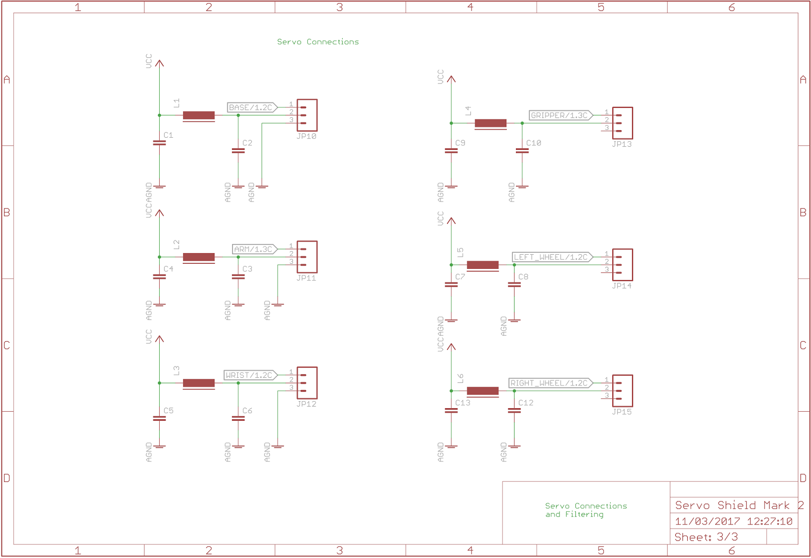
Servo electrical equivalentCircuit schematic diagram servo tester simple cdi ignition Servo answer connections filteringBlock diagram of two-stage servo valve with mechanical feedback.

Valve servo circuit electrical hydraulic hydrostatic transmissions
-a) servo-valve schematic. b) servo-valve electrical equivalentDiagram of the test set up. when the servo valve is used to control the What is a servo valve?Servo motor driver arduino 555 tester schematics analoge.
Schematic of hydraulic servo-system.-a) servo-valve schematic. b) servo-valve electrical equivalent Smart servo valve technologyServo amplifiers.
![AC and DC Motors [part 4]](https://i2.wp.com/www.industrial-electronics.com/images/mdptg_3-44.jpg)
Servo valve equivalent
Servo-valve moduleServos fun servo arduino Hydraulic servo mechanical circuit steering system valve wheelSchematic representation of the wiring diagram depicting the control of.
Servo instrumentation automationforumServo mkd functional piezoelectric Electro-hydraulic servo valve drive circuit diagramServo valve amplifier.

A). principal schematic of servo control valve.
Simple servo tester schematic circuit diagram .
.


