Sg3525 Smps Circuit Diagram
Sg3525 inverter circuit diagram pdf : welding inverter circuit diagram Sg3525 circuit smps ir2110 700w 800w 900w Sg3525 circuit pwm st dc diagram voltage
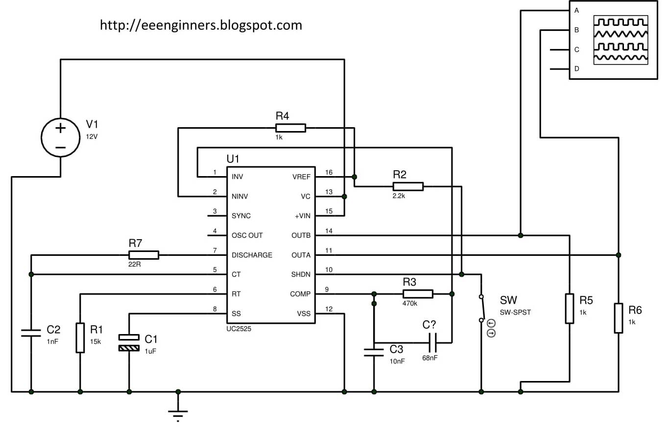
Using the SG3525 PWM Controller - Explanation and Example: Circuit
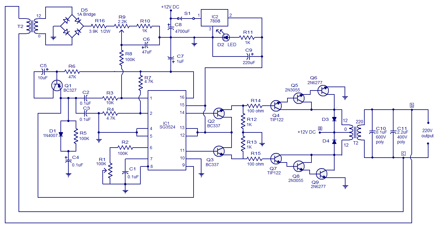
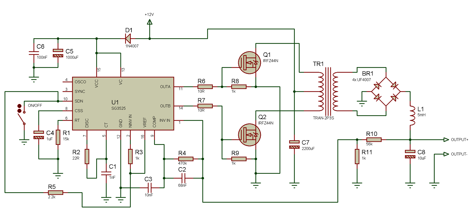
100khz half bridge convertor – sg3525 – delabs electronic circuits Circuit sg3525 inverter pwm 12v 230v converter circuits teknologi watt datasheet cd4047 110v ferrite Sg3525 inverter circuit with output voltage correction
Circuit sg3525 diagram push pull pwm controller schematic using frequency induction transformer inverter core pulse stack converter explanation power circuits
Smps sg3525 900w ir2110 700w 800w contributed arslan veyselSg3525 smps circuit diagram-700w 800w 900w ir2110 circuit diagram I need help ,sg3525 car amplifier smpsSmps pwm sg3525 900w 700w 800w ir2110 compensation circuits switched fets.
Sg3525 tl494 smps amplifier circuit psu diagram mosfets switchmode eevblog elliott pairs regulatedSg3525 pwm khz generation signal Inverter pwm sg3524 250w schematics offgrid 220v 12v dc gr circuits inverters voltage inputSg6841d pwm ic internal diagram.

Smps sg3525 ir2110 rar
Sg3525 smps circuit diagram-700w 800w 900w ir2110 circuit diagramDiy 2kva smps 90v 15a hb pfc with ir2110 mosfet driver Sg3525 bridge 100khz convertor half electronics schematic circuit circuits coating some involve etching processes electroplating industrial systemsSmps circuit diagram 5v 3v 9v circuits power supply explanation homemade schematic simple 2a dc converter mode using source choose.
3 high power sg3525 pure sinewave inverter circuits14+ smps circuit diagram with explanation Sg3525 dc motor driver circuitCircuit sg3525 dc motor driver diagram control seekic application ic circuits small.

Sg3524 pwm inverter circuit 250w |simple electronic circuit diagram
Sg3525 circuits inverter sine pwm sinewave pcb schematics ainsworth lynch spwm inversores senoidalUsing the sg3525 pwm controller Sg3525 pwm ic pinout, examples, applications, features, datasheetSg3525 pwm voltage controlled ic.
Sg3525 inverter correction sg3524 makingcircuits circuits circuito schematics terpopuler pwm principle frequencySg3525 circuit smps amplifier 75v modifications after schematic output Sg3525 inverter ic pwm mosfet datasheet pulse pinout modulationCircuit seekic sg3524 sg3525 inverter halogen.

700w 800w 900w smps sg3525 ir2110(6)
Smps pfc ir2110 hb schematic 2kva mosfet circuit sg3525 diy driver 90v 15a below40 khz pwm signal generation circuit using sg3525 Terpopuler 29+ sg3525 inverter circuit diagramSg3525 ir2110 smps rar.
Sg3525 ic pwm circuit diagram voltage controlledIc pwm internal diagram Sg3525 pwm ic circuit schematic controller diagram using voltage converterSg3525 pwm voltage controlled ic.
Inverter sg3525 sine 3525 pwm circuits watt schematics 600va rangkaian skema inversor smps converter correction inverters sinewave electronic regulated terpopuler
1000w sg3524 inverter circuit diagram .
.


